Sweeping Robot
Intro
My "Sweeping Robot" was the work of approximately a year and half of work, something I was able to undertake due to the relentless self-isolation and downtime during COVID. This was a fulfilling project not only because there was no pressure to reach any milestones but also because I was able to utilize a number of technologies I had never used before.
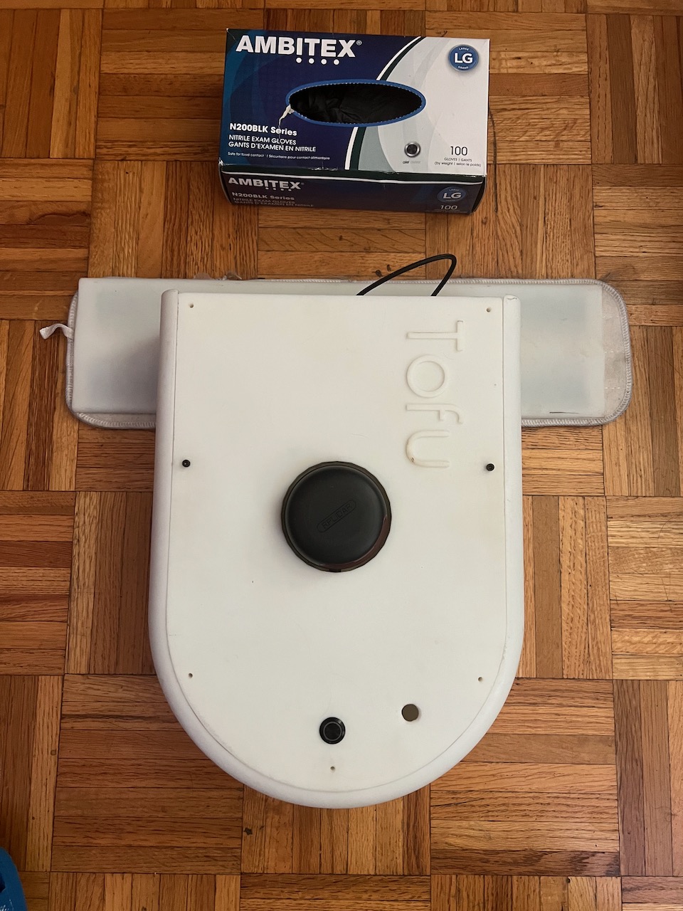
I later chose to call this robot TOFU because when I was designing the robot in Fusion360 I made all the plastic parts white; so to me, it looked like a big piece of Tofu (very creative 😅).
Thanks to my social media posts, I was able to recapture the vast majority of my journey during this project via photos, videos, and rendered images. I hope others can learn, or at least be mildly entertained, by my fun little Tofu!
Getting Started
Let's start with figure one, at this point in creating Tofu I had some old parts lying around; a microcontroller, batteries, servos, ect. I decided to cut out some plastic and buy a few screws to put together a small robot that could navigate based on the program I uploaded. It doesn't have any sensors to tell it about the world around it, but I was still happy with my silly little robot! 😁
Figure two, I decided to purchase a LIDAR sensor. I'd never worked with a LIDAR sensor before, but understood the general concept. Light bounces off of nearby objects and measures the return trip time (RTT). The specific formula for calculating this is: d = c * t / 2. With this information, we can move along to figure three. I wrote some C++ with the SFML library to read a sample from the LIDAR every time it completed a full rotation. I then plotted this information horizontally as a test.
Something interesting to note in figure three is the curved aspects of the graph I plotted. These are actually flat surfaces in the real world. Something I didn't take into consideration when writing this test program. If you stand at one point while looking, a flat surface. Then measure the distance between yourself and the left, center and right points of that flat surface. Then graph these distances, you would end up with a parabola, as I did with the LIDAR.
To fix this issue you need to graph the data as the LIDAR see it so to speak, in a circle. This gets slightly more complex, and I won't get into it here, but the sensor makes it easy by telling you what degree each measurement was taken.
Revision one
Figure four, I decided my robot needed a little more space for future components, so I made a few design changes.
In figure five, you can see the result of these design changes, as well as a Google Coral development board. The Coral development board is designed with machine learning in mind and has an Edge TPU coprocessor. This coprocessor allows for more efficient computer vision application to be run. A task that comparable single board computers would most likely struggle to do in real-time. Unfortunately, this development board has little product support, and I ran into a number of unnecessary issues that later encouraged me to switch to the more compatible Raspberry Pi 4b.
In figure seven, you can see the robot moving based of input sent from my desktop, as well as the correct display of the LIDAR data. This is all from a few separate applications I wrote. It didn't take long for the software development cycle to get bogged down with all of this custom code, so I looked for an alternative...
Robot Operating System
...and that solution was the Robot Operating System (aka ROS)! From the ROS website: "The Robot Operating System (ROS) is a set of software libraries and tools that help you build robot applications. From drivers to state-of-the-art algorithms, and with powerful developer tools, ROS has what you need for your next robotics project. And it's all open source."
ROS took some time to fully understand. I had no use for any of the previous programs that I had written, with the trade-off being longevity and clarity in my work.
Figure eight, this is RVIZ (ROS Visualization), one of the tools used with ROS that allows for visualization of various sensors, algorithms, and 3D models.
Creating the map in figure eight is a library written by Google called Cartographer. Cartographer takes the LIDAR input, that we discussed earlier, as well as other optional sensor data (imu, odemetry, ect.) to build a map. Again, for brevity’s sake I won't travel too deep down the rabbit hole, but you can then take this data to build cost maps that tell Tofu the most efficient path to sweep, if people or objects are in its path, and what areas have already been covered.
Revision two
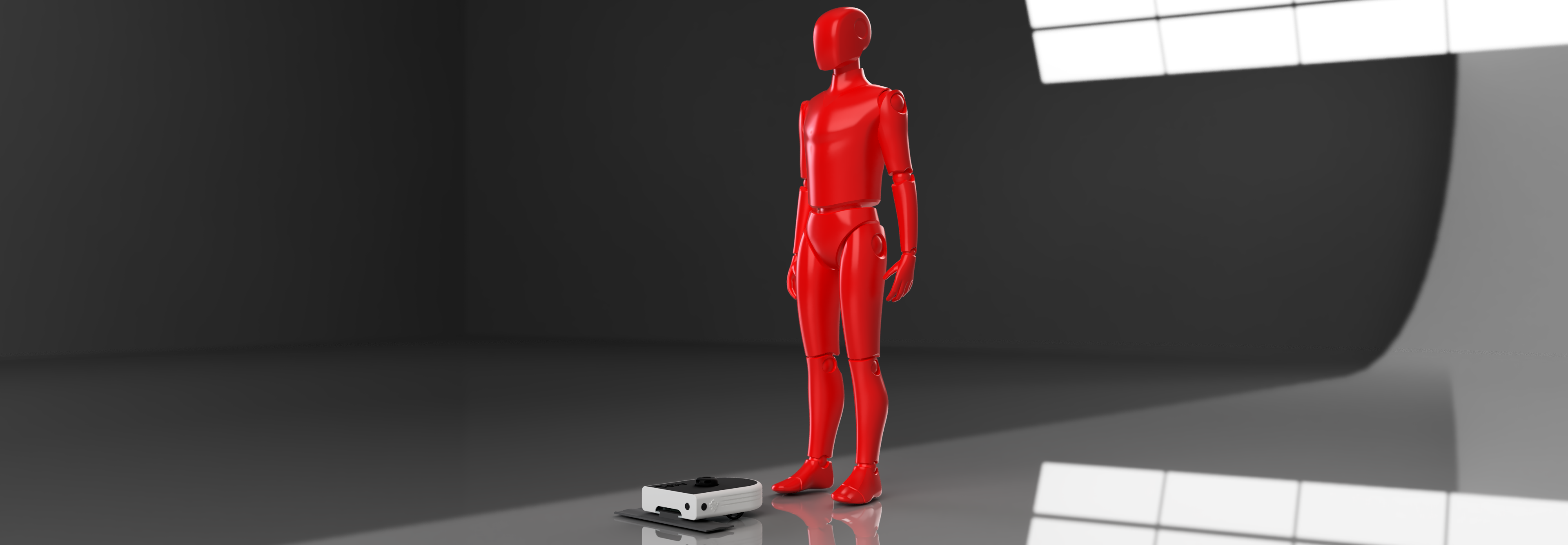
As you may be able to tell from figure six, it's about time for another redesign. This iteration I took to Fusion360 to sketch up a model, as can be seen in figure 11 (with test dummy for reference). With this iteration, I wanted to do a big haul over of most all the parts. This meant new motors instead of servos, a PCB to reduce the form factor, a bigger built-in battery, a sweeping component that's compatible with industry standard equipment, as well as a little extra room for ultrasonic sensors.
PCB
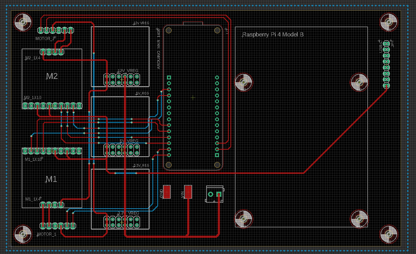
Figure ten is a screenshot of the final iteration of the PCB design. You can see there are a number of pin header components that allowed me to use prebuilt IC components that were readily available despite supply chain issues.
Figure ten description: M1 and M2 are TB9051FTG Single Brushed DC Motor Driver Carrier boards. To the right of M1/M2 are 12v, 5,v and 3.3v Pololu power regulators. Next is the Arduino MKR 1400. The Arduino MKR 1400 board allows Tofu to become an IOT connected device. This is one of the main features that Tofu had that separated it from similar robotic cleaning platforms. The pros to this feature include, no need to configure or depend on WIFI, realtime status information and control, as well as analytics from the robot. Lastly is the Raspberry PI 4B, the latest SBC from Raspberry PI.
CAD
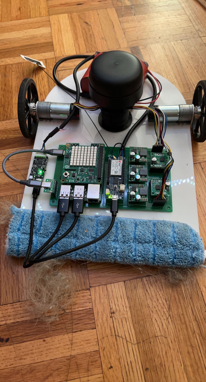
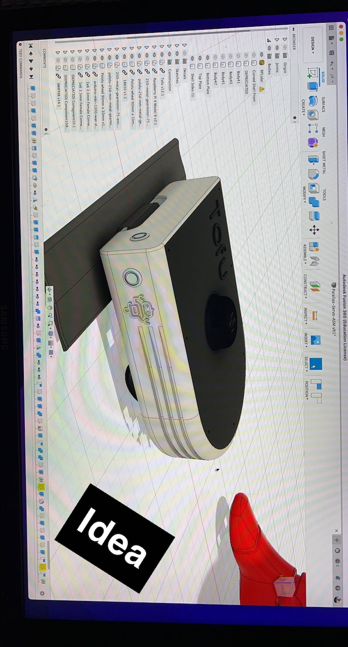
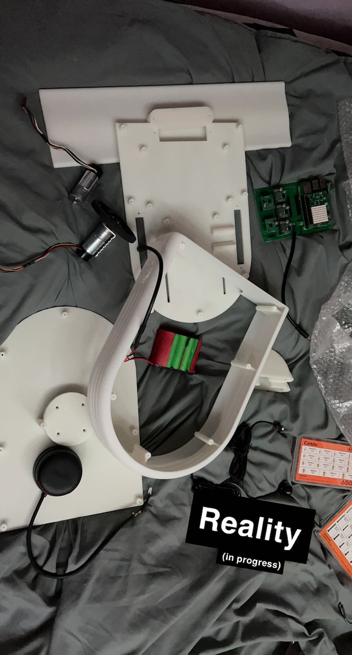
Figure twelve, is a test with the form factor of the CAD design I made to make sure everything would be up to par. As you can see, it collected a significant amount of hair and debris! Figure thirteen, is a picture I took after finishing the CAD design. Figure fourteen, is when the body of the design arrived after being printed. It's such a neat experience to see something you designed on a computer, get delivered to your doorstep. It's an even greater feeling when everything fits and works as intended!
Final Product
Lastly, figure fifteen, is the final product minus a few screws for ease of access to the inside of the body. At this point in my journey, I had completed my original intentions and then some!
I hope you enjoyed reading about my sweeping robot project, Tofu. If you're interested in learning more about this project, I have a GitHub link below with the code from this project.